Sections
- Description Of The Process And Scope Of Application
- Types Of Thermal Degasifiers
- Equipment Description
- Safety Devices
- Control Systems
- Materials
- Start Up
- Frequently Asked Questions
- Sampling And Analysis
- Thermal Degasifier Calculations
DESCRIPTION OF THE PROCESS AND SCOPE OF APPLICATION
The process of thermal degassing is mainly used to treat boiler feed water to comply with the standard UNE-EN 12952-12:2004 in which it is observed, among the limits that must be respected, that the maximum admissible value of O2 for high pressure boilers is 0.02 ppm (20 ppb).
The presence of O2 in the demineralized water fed to the boilers oxidizes the iron in the steel of which they are built, causing the phenomenon called pitting, in such a way that significant corrosion points and leaks occur in the circuits and superheaters inside.
Thermal degassing (TD) is a physical process that consists of removing the dissolved gases in demineralized water by taking advantage of their insolubility at a temperature of 104ºC. The only alternative treatment capable of reaching the O2 and CO2 levels obtained with TD would be chemical treatment with hydrazine (N2H4), amines or Na2SO3, but they have a higher operating cost and, in many cases, these reagents are toxic and unstable.
The TD process in water is based on three fundamental laws that govern the solubility of gases. Henry’s first law says that, at a given temperature, the mass concentration of a dissolved gas in a liquid is proportional to its partial pressure in the solution.
Henry’s Law => p = H·x
Where, p = the partial pressure of the gas.
H = Henry’s constant, dependent on the gas, temperature and liquid, and measured in atm. (mol solute/mol solution).
x = concentration of the gas in the liquid, measured in (mol solute/mol solution).
Another law related to this is Dalton’s law, which states that the sum of the partial pressures of gases dissolved in a liquid is that of the mixture of these gases.
The third law referred to is that which expresses the decreasing solubility of a gas in water as the temperature rises.
Table of solubility of O2 in water against temperature:
| Temperature, (º C) | 10 | 20 | 30 | 40 | 50 | 60 | 70 | 80 | 90 | 100 |
|---|---|---|---|---|---|---|---|---|---|---|
| Solubility O2, (mg/l) | 11.2 | 9.1 | 7.5 | 6.7 | 5.7 | 4.8 | 4.1 | 2.8 | 1.5 | 0.12 |
To thermally degas water, it is sufficient for the container it is in to be maintained under the appropriate pressure and temperature conditions of the saturating vapor, so that the dissolved gases, including O2 and CO2, automatically go into the vapor phase. This is achieved by increasing the pressure in the container to one higher than atmospheric, or by a vacuum pump or eductor, if it is at a lower pressure.
TYPES OF THERMAL DEGASIFIERS
For proper desorption of the gases, the saturated vapor must come into intimate contact with the water to be degassed, which is achieved by giving enough time and contact surface. In this sense, there are two technologies that have been applied:
- Tray degassing
- Spray degassing
Both types have abundant references in industry and the energy field, which is where the boilers that require them are usually found.
An alternative that is not included in this article is vacuum degassing, as the minimum levels of O2 obtained (approximately 0.65 ppm O2) are higher than those required in the water standards for boilers.
The most widespread technology is spray TD because of its construction simplicity and high efficiency (< 7 ppb O2 is obtained, and CO2 is undetectable by analysis).
There is a mixed technique (sprays – trays), which reaches values even lower than this (< 3 ppb), but the equipment is more complex and expensive and is applicable for very demanding uses only.
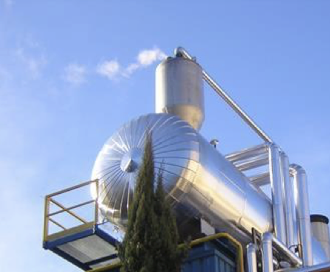
EQUIPMENT DESCRIPTION
A spray type degasifier consists of two main parts:
DOME, composed of:
A chamber containing the demineralized water diffuser sprays and a heater which receives the water spray, and first comes into contact with the ascending vapor from the storage tank. The pre-degassed water is bubbled into a scrubber that overflows into the storage tank. This provides greater water-steam contact; thereby promoting the removal of gases in solution to the required limits (< 0.02 ppm for HP boilers, according to the UNE-EN 12952-12:2004 standard).
STORAGE TANK
This tank must be elevated on a metal structure in such a way that it can be connected to suitable pump inlets, which have a very low required NPSH (1-2 mwc), and thus prevent the negative effect of cavitation.
The tank may be horizontal or vertical, depending on its capacity; usually its independent operating range is 10-30 minutes. If it is horizontal, which usually occurs for degassed water flows > 15 m3/h, support cradles will be available, with one of them being mobile to release the tension due to expansion.
Inside the tank a heating coil with steam is housed to start the equipment.
SAFETY DEVICES
In the area of the dome, an instantaneous evacuation safety valve (type AIT) will be installed, and set at approximately 15% above the operating pressure of the system. A breaker valve is also installed, which may be a simple check valve mounted upside down, to prevent a depression from deforming the equipment.
The storage tank usually controls the overflow by a hydraulic guard of the precise height for the operating pressure (approximately 2.1 m, under the operating conditions considered of 0.21 kg/cm2), or with an overflow control system using an automatic valve. There is also an internal overflow system available.
Both the dome and the tank must be insulated against thermal contact and energy losses.
CONTROL SYSTEMS
The assembly is automated by control valves, one of which will be placed in the demineralized water line to regulate the water flow entering the system according to the storage tank level transmitter signal. In fact, this water will be in addition to the condensate return of supposed continuous flow. However, for safety purposes, an automatic valve should be installed in the condensate line to prevent the possible overflow of this tank. There may also be no condensate return, in which case only the demineralized water to be degassed would be controlled.
The steam supply required for degassing is regulated by another control valve, which will be actuated by the signal from a pressure transmitter located in the dome heater. This will maintain the pressure and operating temperature in the system.
The overflow can be controlled by a hydraulic guard and/or an automatic valve.
The control valves should have their isolation and by-pass valves.
The minimum precise instrumentation for the proper control of the installation will be:
- Thermometer and manometer in the condensate, steam and water supply lines and in the degasser itself.
- Level indicator and transmitter with alarms in the storage tank.
- Overflow level alarm for storage tank.
- Flowmeter for supply water and condensate return.
MATERIALS
The parts of the equipment that contain O2 must be constructed of AISI 316 L stainless steel, although there are cases in which AISI 304 L is used with the usual increased risk of corrosion. The dome and water pipes will be made of that material. The steam pipes and storage tank will be constructed of A-42 b quality carbon steel, or similar.
The storage tank will be sized by taking into account the vacuum according to ASME I and as a pressure device (according to ASME VIII).
PRACTICAL CONSIDERATIONS
START UP
Once the equipment has been assembled, the control parameters adjusted, circuits cleaned and possible leaks checked, it can be started. This begins by feeding the condensate and/or demineralized water to the storage tank and to provide steam via the coil inside. The increase in temperature and pressure will be manually controlled. Then the input water and steam will be automatically controlled, observing that there is no overflow and that the correct operating conditions are maintained.
If there is an overflow, the regulation and action of the demineralized water supply control valve must be checked, as well as that the level transmitter signal is adequate.
The non-condensable outlet will have been set beforehand by calculation, based on the fluid flow; a drilled sleeve type valve is usually used, to avoid overpressure problems.
The automatic valves will be of the NC type, so that if there is any air failure or breakdown, they will remain closed.
FREQUENTLY ASKED QUESTIONS
- Vibrations:
If vibrations are felt, check the suction in the pipes and degassing supports, and that the suction pumps from the tank do not cavitate.
- Irregular input flow:
If it is observed that the water does not reach the storage tank regularly, the sprays may have been incorrectly calibrated, which indicates the importance of precision in this operation, before assembling them in the dome; it may also be due to irregular water supply control.
- Noise in the control valves:
The valves may be outside their Cv and cavitate.
The inlet water pressure control valve must be greater than the outlet by 0.7 kg/cm2 at the operating pressure.
- Water drag due to the exit of non-condensables:
Especially if there is an internal condenser, condensate drag can be produced with the steam and the non-condensables. This is solved with the provision of a simple anti-drag system at the valve outlet.
- Corrosion appears in the pipes, valves or instruments:
Check material certificates and determine in free O2 whether corrosion occurs in the storage tank.
- Overflows frequently occur in the degassed water tank:
Check control loops and level transmitter.
- The pressures or temperatures vary frequently:
See control loop and operation of the pressure transmitter and check local instruments.
- Spills appear in the safety valve:
Check they are set correctly and for possible internal corrosion.
- Why is this equipment usually raised high?
Because we are working at the evaporation limit, height is needed to expand the NHPS available to the pumps that feed the boilers and thus prevent their cavitation.
- Can samples be taken for cold analysis?
No, there is a specific procedure for this explained in the next section.
- Why is condensate sometimes sent directly to the degassed water storage tank?
When the condensate has a high temperature (close to the operating temperature), it is sent directly to the storage tank. This is because there must be a temperature gradient between the water to be degassed and the gas operating conditions of 17ºC at least, for the degassing to be properly verified.
- Within what range is the operation of the degasser reliable?
Between 25% and 100% of the design flow.
SAMPLING AND ANALYSIS
It is quite intuitive to think that taking samples of degassed water to determine O2 and CO2 is not easy, as the solubility of gases is intimately linked to temperature and, if they come into contact with the air, they would become saturated in accordance with their cooling. There are few laboratories in Spain approved to perform the sampling and analysis.
These concepts are controlled by the following regulations:
Sampling:
Sampling: according to ISO 5667-1(UNE-EN 25667-1:1995).
Preparation and handling: according to ISO 5667-3 (UNE-EN 5667-3:1996).
Analysis method:
For O2: ISO 5814 (UNE-EN 25814:1994)
For acid capacity: ISO 9963-3 (UNE-EN 9963-3).
THERMAL DEGASIFIER CALCULATIONS
According to the principle of conservation of energy, the result of adding the incoming and outgoing energies of a system = 0. This is not true for an isentropic process (adiabatic and not doing work).
Energy balance:
Based on the energy balance of a system (incoming energy = outgoing energy) and under constant conditions of operation of the degasser: Operating pressure (Pd) with Enthalpy (Hd) and temperature (Td) obtained from saturated steam tables, resulting from the Molliere diagram, give:
Input flows:
Demineralized water to degas
- Flow rate of demineralized water to be degassed (Qa) in Tm/h at (Ta)ºC
Condensate return
- Condensate flow (Qc) in Tm/h at (Tc)ºC
Steam contribution
- Saturated steam flow (Qv) in Tm/h, at Pressure (Pv) in kg/cm2, with Enthalpy (Hv) and temperature (Tv)ºC, obtained from saturated steam tables.
Outgoing flows:
Non-condensable outflow
- Steam flow rate (Qi) in Tm/h that corresponds with 10% steam supplied to the system (Qv) without internal condenser, or 1% of Qv if there is an internal condenser, to the operating conditions (Hd). With this steam flow, the dissolved gases in the demineralized water (basically O2 and CO2) will be expelled to the outside.
Degassed water
- Degassed water flow (Qat) in Tm/h which corresponds to the Qa + Qc + the condensed steam flow, which will be 99% if there is an internal condenser or 90% of Qv if not. This flow will be at the operating temperature of the system (Td)ºC
Once the operation conditions are set, systems of equations can be established, using their interrelation by the energy balance system. Thus, for example, the following can be calculated from the basic energy balance equation: the steam flow necessary to degas a determined flow of water, the amount of condensate to be returned to a system to obtain equilibrium conditions and the flow of degassed water.
Demineralized water Supply + Condensate return + steam supply = Degassed water + non-condensate outlet + steam flow.
(Qa x Ta) + (Qc x Tc) + (Qc x Ec) = (Qi x Hd) + (Qa+Qc+(Qv-Qi) x Td)
For example:
We want to degas a flow of demineralized water (Qa) = 10 Tm/h, which is saturated with O2 and is at a temperature (Ta) of 20°C. The treatment is proposed with a thermal degasser whose operating conditions are set at a pressure (Pd) = 0.21 kg/cm2 man.
Questions:
Calculate the flow rate of saturated steam at 6.5 kg/cm2 necessary to properly remove O2 and CO2, for a water-tube boiler with a pressure of 40 kg/cm2. Calculate the options for having or not having an internal condenser and commenting on the result.
According to the high-pressure boiler water standards, the O2 content must be < 0.02 ppm with that of CO2 undetectable by analysis, then the technology to be used would be thermal degassing.
To perform the calculation we will use saturated steam tables and the indicated energy balance. Drawing a small scheme is helpful.
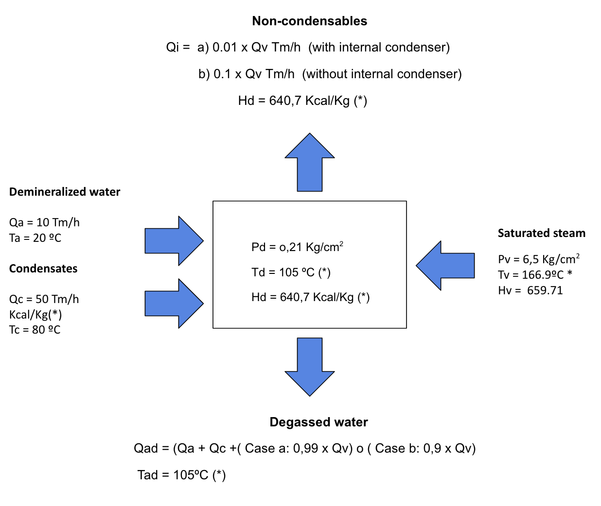
* Values taken from saturated steam tables.
Case (a): With internal condenser
(10 x 20) + (50 x 80) + (Qv x 659,71) = (0,01 x Qv) + ((10 + 50 + (0,99 x Qv)) x 105)
Resolving the equation results in a saturated steam consumption at 6.5 kg/cm2 of 10.37 Tm/h, and a degassed water flow rate of 70.26 Tm/h at 105ºC. The non-condensable flow rate (Qi) is 0.1 Tm/h.
Case (b): Without internal condenser
(10 x 20) + (50 x 80) + (Qv x 659,71) = (0,1 x Qv) + ((10 + 50 + (0,9 x Qv)) x 105)
Resolving the equation results in a saturated steam consumption at 6.5 kg/cm2 of 11.37 Tm/h, and a degassed water flow rate of 70.23 Tm/h at 105ºC. The non-condensable flow rate (Qi) is 1.13 Tm/h.
Comparing both results, it can be seen that the inclusion of an internal condenser saves about 10% steam in this case.
- The steam flow rate with the non-condensables is about 10% of the steam supply flow rate when no internal condenser is used. If used, this consumption is reduced by 1%.
Bibliography:
- Technical water manual (Degrémont)
- Chemical Engineering components (Vian Ocón)

